
Layering and Linework Formatting
Well organized and formatted layers to provide ease of filtering layers and illustrating the desired information.
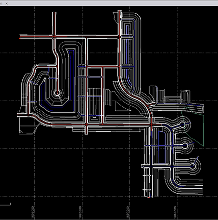
Layering
My projects only include the layers you request, such as breaklines, centerlines, flow lines, boundaries, utilities, property lines, etc. Each layer has a unique color to assist with operator recognition.
Many times when getting linework from the engineer they may give you their entire drawing file which contains enough data to make your display lag and slow processing. Filtering out unwanted layers will not only help the operators focus on what is important with a well illustrated display, but it will improve the processing of the program.


3d Linework
Your project's linework is essential to the understanding of the location of items of interest, such as breaklines, perimeters, curbs, property lines, and even material changes. Engineers mostly give the contractor 2d Linework, which works ok on a map view, but provides no design elevation information.
Linework such as a curb flow line, or culvert invert should be able to be measured in the field. I make sure all the functional linework is elevated and measurable. You can, for example, select the culvert line to measure, and excavate to the given elevation of the culvert's invert at any distance along it, even though it is under the TIN surface. Measured locations of utilities? I can add 3d avoidance to those zones as well.
The Process of Point Cloud Modeling
Point cloud modeling involves several steps, and I have expertise throughout every stage to create better outcomes for your projects. Here’s an overview of the steps involved in 3D point cloud modeling.
1
Initial Assessment and Planning
Point-cloud modeling begins with initial assessment and planning on your job site. During this stage, you may study maps and other resources to collect information about the building site. Information may include vegetation, soils, existing infrastructure and the geography of surrounding areas.
This information gives you a background to aid your decision-making throughout a project. Once you have some basic information, you can move to point cloud data collection. You must decide which collection method to use and how to analyze the information once collected.
Point Cloud Data Collection
2
After initial assessments and planning, point cloud data collection can begin. The process uses remote sensing or surface reconstruction. Remote sensing involves lasers mounted to drones, while surface reconstruction uses cameras to capture information about a site.
Site surveyors fly drones or airplanes above the construction site to collect the data. The collected point cloud data is stored in a file format like PTS, XYZ, E57, LAS, PTX or PLY. Some of these file formats are universal and work with various point cloud analysis software.
3
Point Cloud Data Analysis
Once site surveyors collect point cloud data, engineers and 3D techs use software programs like Autodesk AutoCAD, ARES Commander, Trimble SketchUp or Autodesk Revit for point cloud data processing. They transform it from a collection of points to a point cloud. The solution chosen may depend on the format of the data stored and the model you wish to create.
Data analysis involves merging several individual datasets since point cloud scans overlap angles and mapped areas. When engineers combine these datasets, they create one accurate point cloud.
4
Point Cloud Model Creation
Once engineers generate and refine point cloud data, they can create a CAD or BIM, depending on your preferred format. The 3D model provides detailed information about the site’s terrain, elevation changes, vegetation and other features. This data serves various purposes, including everything from machine control to project tracking.
3D and GPS Machine Control Modeling Services
The benefits of machine control are what make this breakthrough in earthwork machinery so popular. When carried out correctly — in conjunction with high-quality 3D machine control models — it typically provides the following advantages:
-
Increases heavy-duty machine efficiency and productivity.
-
Decreases operating expenses such as fuel, repair and maintenance costs.
-
Reduces raw materials costs by using them more effectively.
-
Lowers surveying costs by eliminating ongoing grade checking.
-
Reduces labor costs by increasing individual worker efficiency.
Of course, for any machine control project to be successful, the 3D model it’s working off must be accurate and complete. That’s why more and more construction companies are turning to 3D machine control modeling services — like those we provide at TOPS — to bid on, accept and complete more projects with confidence and proficiency.


3D AND GPS MACHINE CONTROL MODELING SERVICES
Our commitment is laser-focused on rendering purpose-driven, precise machine control models. Our experienced in-house team transcends the common industry practice of using subcontractors, ensuring we deliver competent 3D model machine control solutions. Our engineers are available across all major U.S. time zones for consistent national service, a critical factor for timely project bids and proposals.
3D AND GPS MACHINE CONTROL MODELING SERVICES
With over two decades of expertise in delivering GPS machine control modeling, our commitment to accuracy and detail is evident in our strong performance record. Annually creating approximately 1,000 high-quality machine control models, we strive for exceptional turnaround times and unwavering client support.